

New Products
- HYRM-27 Underground Gas Insulated Enclosed Metal Switchgear | 25kV, 1200A, IP66, UL 2914 Certified

- 12kV Fully insulated inflatable ring switch equipment

- 36kV AC metal enclosed ring network switchgear SF₆ Gas-Insulated Metal-Enclosed Switchgear (GIS)
")
- SF₆ Insulated Ring Main Unit (RMU)
")
- 24kV Solid Insulated Ring Main Unit


XGN66-12kV Box-type fixed closed Switchgear
Model: XGN66-12KV Switchgear
CNKEEYA,XGN66-12kV Box-type fixed closed Switchgear, a distinguished supplier based in China, is renowned for delivering high-quality electrical solutions, with their XGN66-12KV Switchgear standing out as a prime example. As a key player in the industry, CNKEEYA continues to set the standard for quality and innovation, providing customers with cutting-edge solutions for their electrical infrastructure needs.
In the realm of high quality electrical solutions, Keeya, based in China, XGN66-12kV Box-type fixed closed Switchgear, stands out as a reputable supplier, exemplified by their advanced XGN66-12KV Switchgear. Engineered with precision and adhering to stringent quality standards, this switchgear reflects Keeya's commitment to excellence in the field. The XGN66 series showcases cutting-edge technology and superior craftsmanship, making it a reliable choice for electrical distribution systems. As a key player in the industry, Keeya continues to contribute to the advancement of power infrastructure with their state-of-the-art switchgear solutions, ensuring efficient and reliable performance in diverse applications.
XGN66-12 box type Fixed closed switchgear (hereinafter referred to a s switchgear) is suitable for 3.6~12kV three- phase AC 50Hz system as the device t o receive and distribute electric energy, it's used for frequent operation places and for reconstruction of switchgear equipped with oil switch. The bus system consists of single bus system and single bus section system.
Service condition
● Ambient temperature: maximum +40°C, minimum -15°C;
● Altitude: not more than 1000m;
● Altitude: not more than 1000m;
● Relative humidity: daily average no more than 95%,monthly average no more than 90%;
● Earthquake magnitude: 8 or less;
● In place of no Pre or explosion risk,no serious pollution,no chemical corrosion and no violent vibration.
Technical parameter
|
No. |
Item |
Unit |
Technical prameter |
|
1 |
Rated voltage |
kV |
3.6,7.2,12 |
|
2 |
Rated current |
A |
630,1250 |
|
3 |
Rated short circuit breaking current |
kA |
20,25,31.5 |
|
4 |
Rated short circuit closing current |
kA |
50,63,80, |
|
5 |
Rated short time withstand current(4s effective value) |
kA |
20,25,31.5, |
|
6 |
)Rated peak withstand current(peak) |
kA |
50,63,80, |
|
7 |
1min power frequency withstand voltage |
kV |
42 |
|
8 |
Lightning impulse withstand voltage |
kV |
75 |
|
9 |
1min power frequency withstand voltage of auxiliary circuit |
kV |
2 |
|
10 |
Protection level |
|
P3X |
|
11 |
Outline size(cable outlet W×DxH) |
mm |
900×1000×2200 |
Product structure
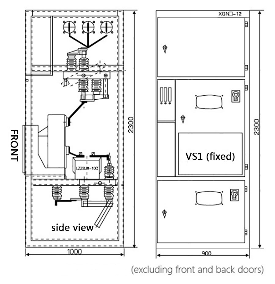
● Schematic diagram for switchgear (Figure 1)
● The switchgear is a box-type fixed structure,and the switchgear body is welded by thin plates and angle iron. The upper part of the rear of the switchgear is the main bus compartment,and the top of the compartment is equipped with a pressure release device; the upper part of the front is a relay compartment, and the small bus can be connected from the bottom of the compartment with a cable. The middle and lower parts of the switchgear are connected. The bus compartment is electrically connected to the middle and lower part through the GN30 rotary isolating switch; the middle part is installed with a vacuum circuit breaker, and the lower part is installed with a grounding switch or an outlet side isolating switch; the rear part is installed with a current transformer,a voltage transformer,and a lightning arrester. The primary cable exits from the lower part of the rear of the switchgear; A grounding bus is arranged at the bottom of the switchgear, which runs through the entire row of switchgear; the isolation switch and the grounding switch are operated at the front left of the switchgear.
● The switchgear adopts the corresponding mechanical locking device,the locking structure is simple, the operation is convenient, and the Pve preventions are reliable.
● Only after the circuit breaker is actually disconnected,the handle can be pulled out from the "working"position and turned right to the "disconnecting"locking position to open and close the isolating switch,which prevents the opening and closing of the isolating switch from being loaded.
● When the circuit breaker and the upper and lower isolation are in the closed state and the handle is in the "working position',the front switchgear door cannot be opened to prevent accidental entry into the live compartment.
● When the circuit breaker and the upper and lower isolating switches are both in the closed state,the handle cannot be turned to the "Maintenance"or "breaking lock"position to avoid accidental opening of the circuit breaker.When the handle is at the "breaking lock"position,with only separate the upper and lower isolation,however,the circuit breaker cannot be closed,avoiding the mistaken closing of the circuit breaker.
● When the upper and lower isolation is not opened,the grounding switch cannot be closed,and the handle cannot be rotated from the "disconnecting and locking"position to the "inspection"position,which can prevent the live ground wire from being hooked. Note:According to different switchgear solution,some solutions do not have the lower isolation,or the lower isolation is replaced by a grounding switch,and the lockout and Pre preventions can meet the requirements.
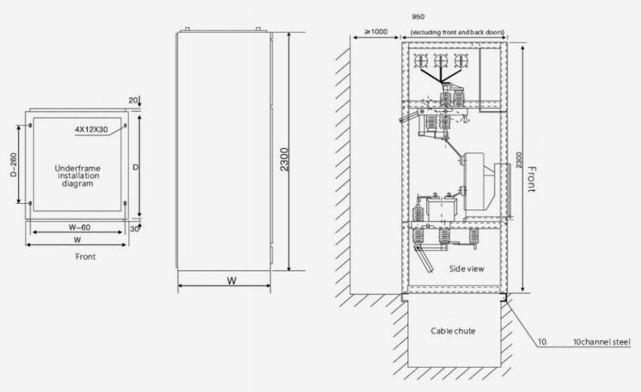
Installation size and basic diagram
● Refer to Figure (2)for the installation foundation,the foundation channel steel protrudes 1-3mm from the ground,the unevenness per meter should not exceed 1.5mm,and the full length should not exceed 5mm.
● Place the switchgear on the foundation in order and adjust the installation position.Then Px it with M12 bolts or spot welding, and tighten the switchgear with M8 bolts.
● After disassembling the cover plate to install the main bus and primary cables,the contact surface of the terminals should be cleaned and coated with neutral petroleum jelly.After installation please block the primary cable hole.
● Connect the indirect ground bus bar of the switchgear to make it into one body along the arrangement direction of the switchgear. Check whether the grounding is missing,whether the grounding loop is continuous,and the grounding resistance should not be greater than 10.
● Install the secondary cable.The cable is introduced from the bottom of the front of the switchgear,enters the relay room along the side wall,and is tapped on the terminal block;after installation,the cable hole should be blocked.
● Clean up the dust and debris inside the switchgear.
Delivery information
The manufacturer shall provide the following documents and attachments when supplying:
● Shipping list;
● Product quality certificate and factory test report;
● User manual;
● Relevant electrical drawings;
● Main components manual;
● Cabinet door key,operating handle and spare parts specified in the contract.
Switch cabinet outline size
Ordering instruction
● Primary wiring solution diagram and primary wiring solution arrangement diagram.
● Secondary circuit schematic diagram,wiring diagram,terminal wiring diagram.
● List of primary and secondary equipment.
● Switch cabinet layout and bus and cable tray location.
● Please negotiate with our company for any special service condition of spare part and equipment.
Hot Tags: XGN66-12kV Switchgear, China, Manufacturers, Suppliers, Factory, Quality, Wholesale
Send Inquiry
Contact Info
-
Address
No. 68, Wei No.19 Road, Yueqing Economic Development Zone, Yueqing City, Wenzhou City, Zhejiang Province,China
-
Tel
-
E-mail
For inquiries about Distribution Cabinet Shell, Circuit Breakers, Switchgear or price list, please leave your email to us and we will be in touch within 24 hours.


